

The Display Technology
First off, something everyone should understand is that there are different display technologies. The two different display technologies are Transmissive and Emissive. The main difference between the two is whether or not they actually generate light.
- Transmissive: Light is not generated, but is passed through an object to create an image. It is reflective and creates an image by bouncing off a given surface that is perceived by the viewer.
Displays that use transmissive technology: LCD, front, and rear projection - Emissive: Light is generated by individual elements which combine to create an image.
Displays that use emissive technology: LED, Plasma, OLED
Here, we’ll be focusing on only the emissive display technology, specifically Direct View LED – referred to here as “dvLED”.
Why dvLED is Revolutionary
LED technology is not necessarily “new”; however, due to advancements in technology, we are able to provide solutions that have previously required architects, engineers, and general contractors to provide a single video display.
Another advantage of LED and/or dvLED is its brightness and contrast. As mentioned, LED, and dvLED displays are an emissive technology. This provides images that are brighter and higher in contrast than the transmissive technology of traditional LCD displays or other transmissive displays. This also allows for a wide viewing angle, and helps overcome nearly any ambient lighting condition.
Other benefits that dvLED provides are: the ability to have a seamless large-screen and/or wall display, the ability to have a curved design, and dvLED designs are modular based – allowing for almost infinite configurations!
Terms You Should Understand
Before we talk about the types of dvLED, let’s define a pixel, and what the term “pixel pitch” means.
LED: A light emitting diode (LED) is a tiny, electronic semiconductor that converts electric energy into visible light. The chemical compound used within an LED determines its color, brightness and power efficiency. Each full color pixel in an LED display is comprised of 1 Red, 1 Blue and 1 Green LED.
Pixel: A “pixel” consists of a group of individually mixed colors that combine to represent a colored element. This pixel, when mixed with other pixels, combines to make an image. In a dvLED display, each pixel consists of a physical Red, Green, and Blue LED.
Pixel Pitch: The “pixel pitch” is the physical measurement of an LED cluster, the pixel’s center, and the distance between the adjacent pixel’s center. This distance is measured in millimeters. The smaller the distance between each LED pixel, the more pixels on the display to create the image. This increases the display’s resolution allowing for more detail to be seen in the image. This clearer image allows the optimal viewing distance to be shorter.
Pixel pitch example: a pixel pitch of 1.9mm would be 1.9mm from the center of one 3 LED pixel cluster to the center of the next 3 LED pixel cluster.
Pixel Density: The”pixel density” is the number of physical pixels within a given area – usually expressed by number of pixels per inch. Pixel density directly corresponds to ‘pixel pitch’ in that the higher the pixel density, the smaller the pixel pitch is (megapixels per cm(2)).
Types of LEDs
Primarily there are 3 main types of LEDs used in large dvLED displays – with a few very specific differences between the technologies that define how large or small their physical size can be.
- Direct In-Line Package (DIP) LEDs require two physical contacts (anode and cathode)
- Surface Mount Diode (SMD) LEDs require either 4 or 6 physical contacts (3 anodes, and one common or 3 individual cathodes)
- Chip On Board (COB) LEDs can be printed onto a PCB and connected with a ribbon cable or an integrated connector that includes hundreds of connections
See Figure 1 for a comparison of the 3 primary LED technologies. As you can imagine, the larger the elements, the easier they are to assemble and service; the smaller the elements, the harder it is to see the individual pixels, yet cost and serviceability become large factors.
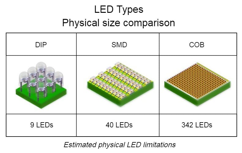
Figure 1: physical LED size comparison between various solutionsLet’s assume we have a digital billboard, with a standard 14’x48’ dimension and a pixel pitch of 20mm for an overall resolution of 208 pixels x 720 pixels. While this resolution may seem low for such a large image, the distance a viewer is from the content is more than adequate to display the image.
Why Are Different LED Solutions Important
The primary factors in deciding which technology is right for you are 1) pixel density – the number of physical pixels within a given area, and 2) the overall cost. As we start to integrate dvLED displays in a professional AV environment where closer viewing is required, we must decrease the pixel size and increase the pixel density. Reducing the pixel size will increase overall resolution, making the individual pixels smaller and harder to see, therefore making the picture more clear. These two factors (pixel density and cost) are directly related: as your pixel density increases, as will the cost of your display; as your pixel density decreases as will the cost of your display.
As shown above, there are different types of LED solutions: DIP, SMD, and COB. They each have a different pixel pitch.
DIP LEDs, for example, reach a physical limitation as you reach a 10mm pixel pitch. The same can be said for SMDs but at a much smaller pitch of roughly 0.9mm. COBs can achieve pitch beyond 1mm pitch, but the cost increases dramatically. The primary dvLED solution offered today is SMD technology, as there are varying pixel pitches from 0.9mm to 3.5mm 3.5mm to 0.9mm at a reasonable price point for the entire solution.
In Figure 2 and figure 3 we show examples of varying pixel pitches of SMD pixels on a pixel card. Note the physical pixel is the same size on either pixel card; however, the pixel density is increased and in turn decreases the pixel pitch. On the left, an example of a 1.2mm pixel pitch card; and on the right, an example of a 1.9mm pixel pitch card.
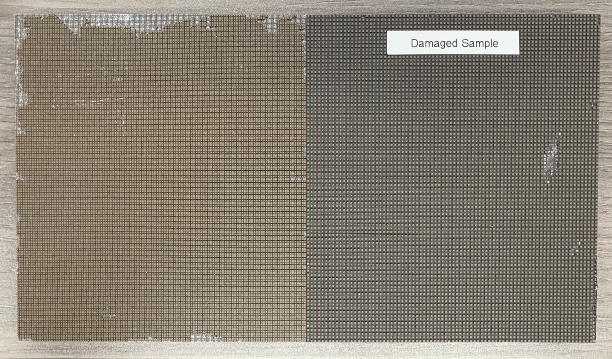
Figure 2: on the left, a 1.2mm pixel card; on the right, a 1.9mm pixel card
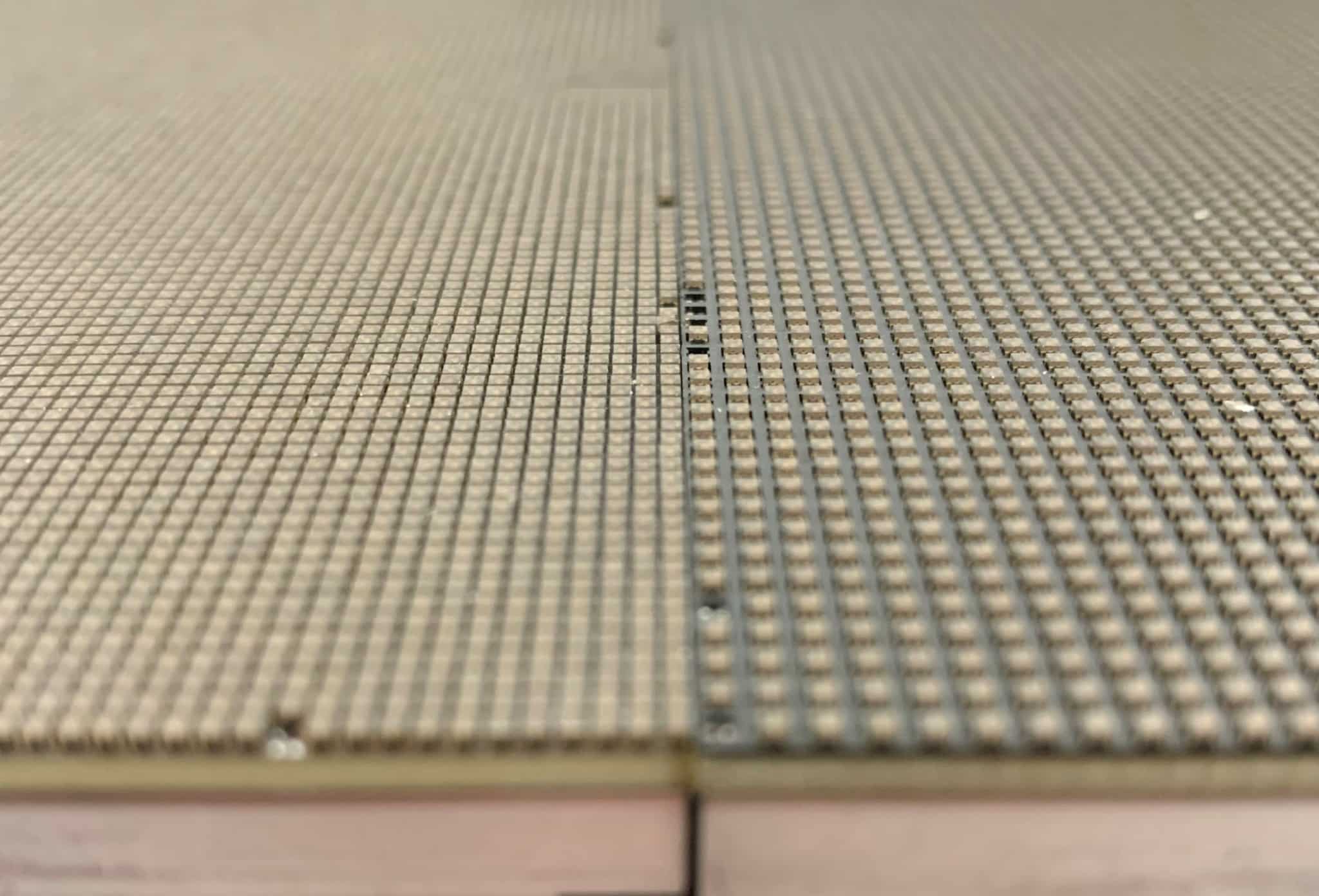
Figure 3: on the left, a 1.2mm pixel card; on the right, a 1.9mm pixel card
What Pixel Pitch Do I Need
When designing a dvLED display, it is best to determine your space for its average comfortable viewing distance. Viewing distance is directly related to the pixel pitch by using the 10x Rule, sometimes referred to as Rule of 10, or by using the more precise visual acuity distance calculation. The 10x rule helps determine what pixel pitch should be used at an average viewing distance whereas, the visual acuity distance formula can be used to determine the ideal viewing distance for a given pixel pitch.
10x Rule: Average viewing distance (in feet) should be around 10x the pixel pitch. While this estimation is not precise, or to be used when designing your system, it will give you a great base to achieve budgetary numbers.
Example in use:
- If you need a display in a lobby that has an average viewing distance of 35 feet, then a 3.5mm pixel pitch is adequate
- For a conference/training room where the average viewing distance is 12 feet, then 1.2mm would be an adequate pixel pitch.
Visual Acuity Distance: Although we can get an idea of the pixel pitch to be used at a given distance, we can become even more precise by determining the best viewing distance and/or range for a given pixel pitch. For this, we determine the Visual Acuity Distance by using the formula: (Pixel Pitch x 3438)/304.
Here’s why: Pixel pitch (in mm) is multiplied by 3438, which is a scale factor of one arc minute for a person with 20/20 vision. Then, once those numbers are multiplied together, we divide it by 304 which converts it from mm to feet.
Example in use:
- A panel that has a 2.0mm pixel pitch has a Visual Acuity Distance of 22.6ft. With the 10x rule estimation, however, we’d get a 20ft estimation. ((2.0(mm) x 3438)/304 = 22.6ft)
Now that you understand how we achieve the average viewing distance, we can provide a range by adding or subtracting half of the average viewing distance. In the 2.0mm pixel pitch example, we can achieve an average viewing distance of 20ft, with a range from 10ft-30ft of comfortable viewing. A smaller pixel pitch will reduce those ranges for a smaller viewing area such as a 1.2mm pixel pitch, 12ft average viewing distance and a comfortable viewing range from 6ft to 18ft.
Don’t worry. If this doesn’t make sense, just know that the 10x Rule is based on the formula: (Pixel Pitch (in mm) x 3438)/304 – which ends up being roughly 10x. Similarly, to get the rough range, just multiply the minimum and maximum viewing distances and multiply them by 10.
If your primary viewers are less than 9 feet, or in a specialized application where there is an increased requirement for contrast, you may need to explore using COB LEDs as your display type. See Figure 4 for an example of a COB LED. Even though the physical pixel size is under 0.1mm, the pixels themselves are spaced out to allow for an increased black level when no signal is present. This solution is well suited for cinema applications, analytical data, screening rooms, and many other applications that require a high level of image accuracy.
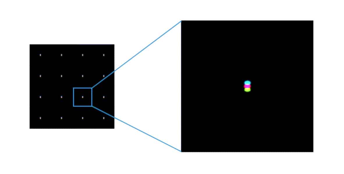
Figure 4: COB LED reference showing a sub 0.1mm pixel size, with an overall pixel pitch of 1.2mm
Interpreting a Signal & Set-up
Regardless of which type of LED technology that is used, there needs to be a way to get the content from a generic video standard, such as HDMI, DVI, or SDI, to a signal that your LEDs can interpret. For this, an LED controller is necessary.
While some manufacturers have developed their own solutions, the most widely used products are developed by NovaStar. A NovaStar processor will take your video signal, and give you proprietary CAT6 data feeds to send to your pixel cards. These pixel cards are stacked up, through cabinets, that house the components needed to drive your LEDs.
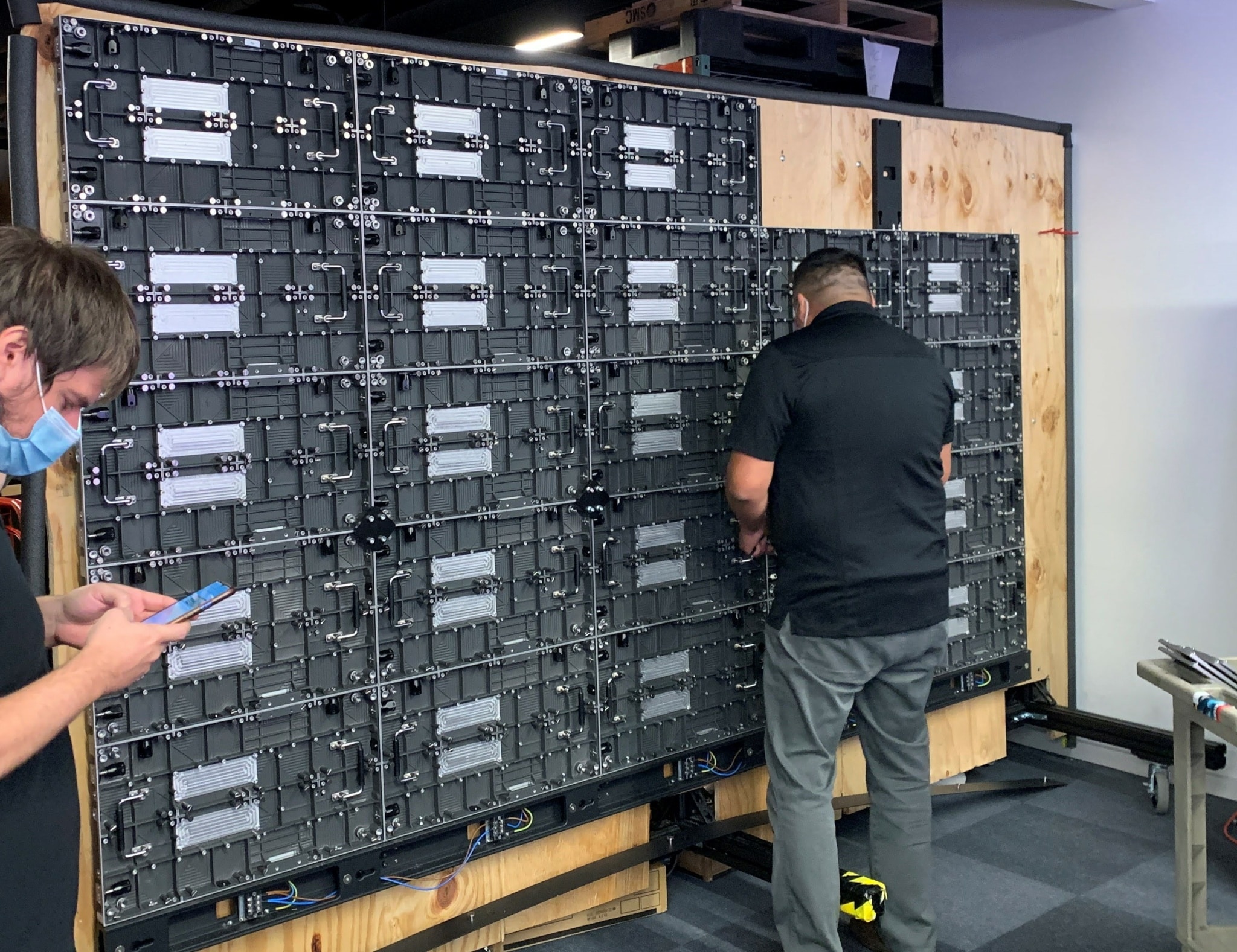
Figure 5: an example of a dvLED cabinets in a 135” configuration without any populated pixel cards
Once the cabinets are mounted to the wall, power is supplied to the wall through the main power bar located at the bottom of the display, video signals are routed through the cabinets – as specified by the wall’s configuration, and pixel cards are populated individually to fully cover the display’s footprint.
Some applications may require you to show a single image, multiple images, or even picture-in-picture layouts. For these applications, the addition of third party components such as matrix switchers, scalers, or video wall processors may be required to ensure your dvLED wall can display the image – or images – correctly and appropriately to fit your needs. While this type of processing is not a native feature of the video wall or dvLED controllers, it is definitely a possibility when designing your entire solution.
In summary, even when discussing Direct View LED (dvLED) there are multiple options to choose from. Its long-lasting lifespan and cost should not be the only consideration. Other features such as viewing distance should be considered when deciding what pixel pitch and density will work best for your needs; a way to interpret a standard signal and display a picture how it’s wanted is also needed.
Call us today at 801-486-5757 (M-F 9am-6pm) for more information on Direct View LED displays and to discuss what solutions and services TVS Pro can offer you.


0 Comments